Manufacturer of Resistive | PCAP Touch Screen | PenMount Touch Screen Controller - AMT
Certified resistive, projected capacitive (PCAP) touch screens and PenMount touch screen controllers meeting international standards, ISO, UL E331240-A1-UL, REACH, and RoHS. All touch screen products are supplied with flexible production quantity and long term support. Over 20 year experience in touch panel industry. Supplies touch displays, optical bonding, touch panels, touch controllers, ePaper display solutions, open frame monitor products. Based in Taiwan, AMT is a manufacturer of touch displays, optical bonding, ePaper display solutions, touch screens, touch controllers, and open frame monitors for the industrial, medical, and commercial sectors. since 1998.
Welcome to AMT
AMT was established in 1998 in Taiwan. We have extensive experience in the design, development, and production of touch solutions and we are committed to supplying touch displays, optical bonding, ePaper display solutions, touch screens, touch controllers, and open frame monitors.
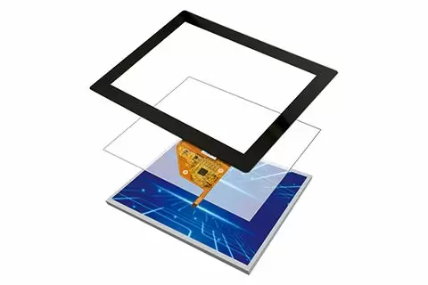
Optical Bonding Service
In-house manufacturing, offering one-stop services• Utilizes OCA bonding process
• Suitable for various displays
• Supports curved or multi-screen bonding
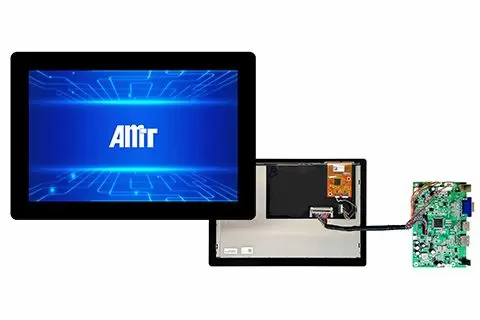
Sigma Touch Display
Simplified supply chain, available in sizes 7" - 21.5"• LCD brightness: 500 or 1000nits
• Industrial grade specifications, anti-UV design
• Easy integration into systems
ePaper Display Solution
EPD or Ch-LCD module optical bonding services• Integrated front light guides and light bars
• Applies anti-IR film
• Provides UV protection

Mission & Vision
AMT is dedicated to quality. AMT's unique value lies in its ability to fulfill the diverse needs of customers.

Environmental & Energy Policy
AMT is committed to environmental conservation and the perpetuation of green energy.

Quality Certification
AMT has obtained ISO 9001: 2015, ISO 13485: 2016, ISO 14001: 2015, ISO 45001:2018, UL, REACH, and RoHS certifications.